
Home : Workshop : CNC :
 This topic covers squaring a CNC X-axis to Y-axis using slightly modified versions of the two and five cut methods commonly used to accurately square fences to sawblades. It also covers setting, checking and maintaining squareness using faceted stop screws.
While the article is pretty wordy (which makes the method seem complicated), it's a by the numbers approach that does not rely on any eyeball alignments or measurements. It is a relatively simple method to get and maintain 90 +/- .01 degree accuracy (+/- .1mm over 1m). In theory, the maximum possible accuracy is better than a full step, e.g. < .04mm over 1m (8mm pitch/200).
The first step is to set a fence parallel to the Y-axis. I have a semi-permanent fence and various sacrificial secondary fences. The fence that will be used for squaring needs to be solidly mounted and routed in place with a small (e.g. .25mm) finish pass to insure there are no deflection issues, that it is truly parallel to the Y-axis.
The next step is to clamp down a large a piece of material tight against the fence. Route the front edge, also with a small finish pass. There are now two options. If you know the sides of you workpiece are straight and parallel you can flip the piece over (side to side) and clamp it back down (two-cut). Otherwise, and if you want higher potential accuracy, rotate the workpiece so that the edge you just cut is against the fence and clamp it down. Cut and rotate the front edge a total of four times (five-cut).
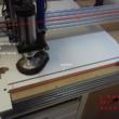
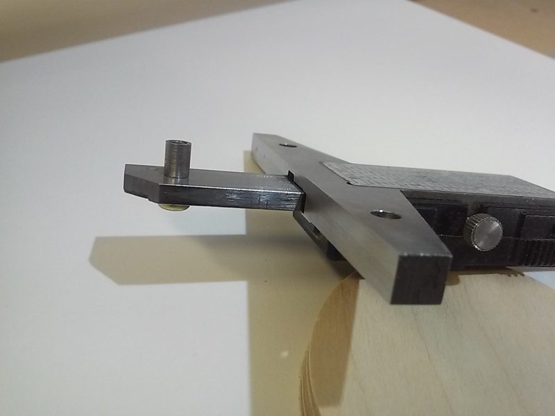
Next cut a pocket (second/fifth cut) that is wide and deep enough to accurately measure the distance between the front edge of the workpiece and front edge of the pocket (I don't need much for the pin on my calipers). When squaring a fence to a saw blade this cut would be full depth leaving a strip of material. With a router, cutting a pocket allows a small finish pass and insures there is no inaccuracy due to deflection. If needed, the strip could be through cut at the back of the pocket, i.e. some distance away from the front of the pocket.
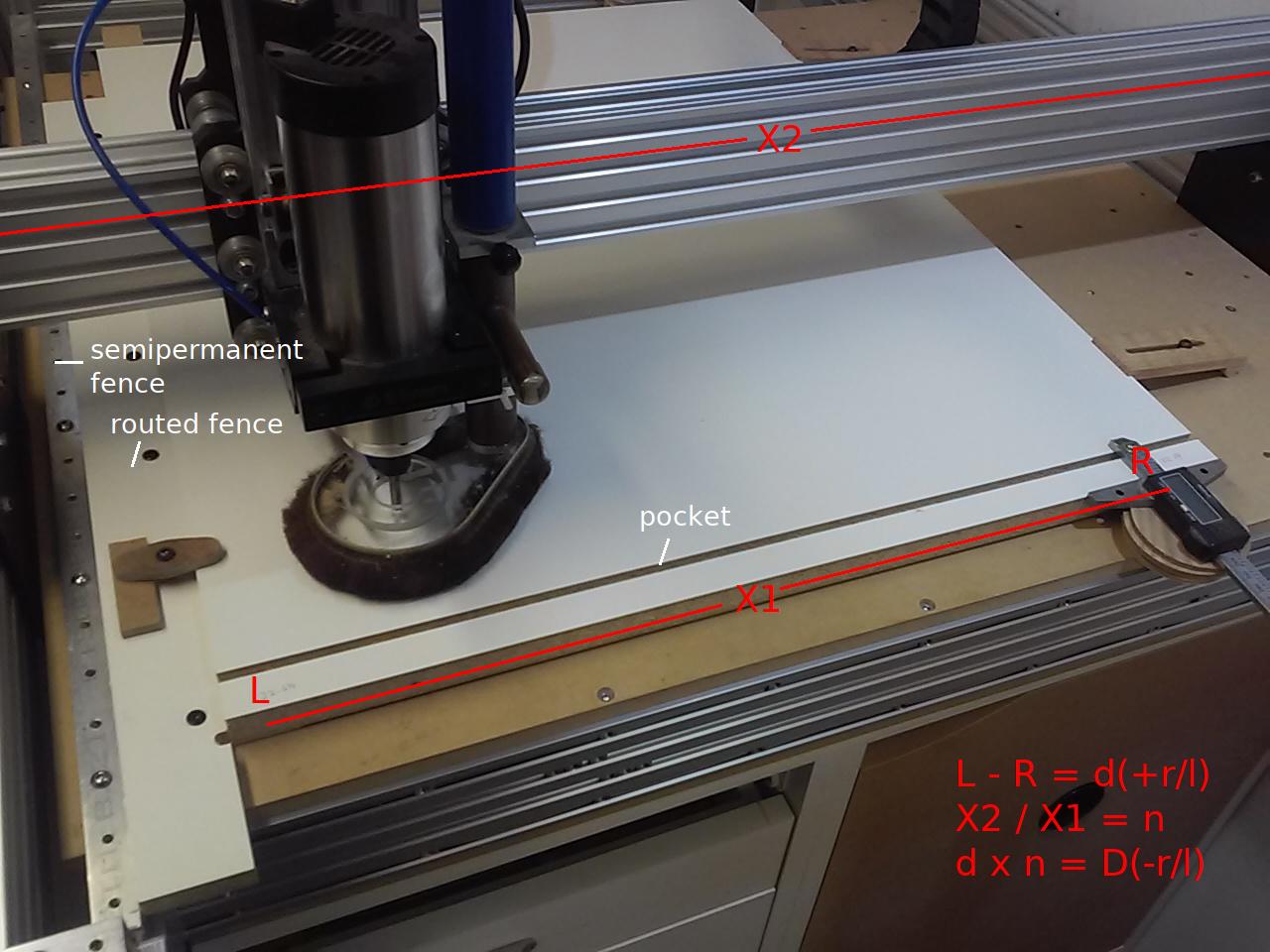
Measure the width of the strip at both ends (L/R) and subtract the measurements to get the difference (d) and note which end is bigger (e.g. dr). Measure the distance between the two measurements (X1) and the length of the gantry (X2). Divide X2 by X1 and multiply by d(r/l) to determine how much the right/left end of the gantry needs to be moved forward (D), e.g. 1012 (X2) / 595 (X1) = 1.70, 1.70 x .7 (dr) = 1.19 (D). In the example the right end of the gantry needs to be moved forward by 1.19mm (D- right) to square the machine.
As usual there are probably a heck of a lot of ways this could be done. Disabling a stepper (e.g. left) and moving the gantry forward (e.g. 1.19mm) would be an accurate one shot way, not a practical solution. Rotating a stepper x number of degrees (e.g. 53.57 = 1.19 w/ 8mm pitch) seems totally impractical. Measuring and adjusting the gantry end plate to Y end plate distance seems the most practical, but how to do it accurately and easily.
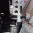
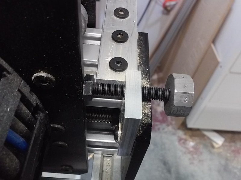
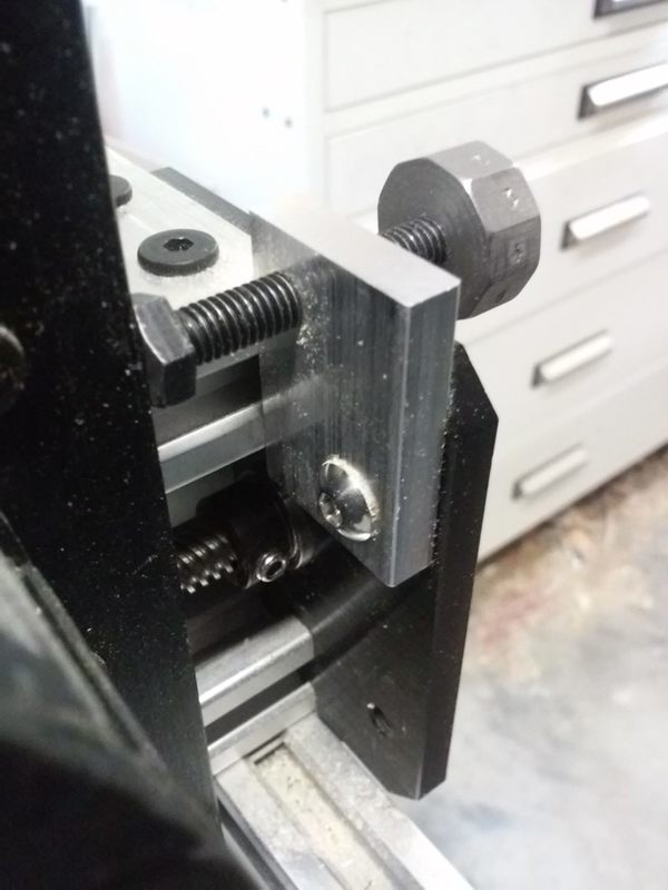
[ link | top ] My solution for setting/checking/adjusting X-axis squareness is M6 x 1mm pitch stop screws with an adjustable 10 facet 'head' with 1-9 numbers stamped on the facets (.1mm travel per facet). The actual heads are faced flat and the faceted 'heads' are locked to the screw threads using a set screw (0 position). The screws are mounted to the front Y-axis plates via a threaded aluminum plate with a hole for screw mounting to one of the threaded motor mount holes. The center of the stop screw head pretty much centers on the edge of the X-axis plates.
Note: Steppers/screws can move ever so slightly (<1.8 degrees) when turning on the drivers. This happens when the steppers move from a stopped micro step position to a full step start position. Because of this I do all settings and adjustments from the just turned on position.
For the initial stop screw setup the gantry is moved into reach of the stop screws, the drivers are turned off and back on, the stop screws are rotated until they contact the gantry plates, the 'heads' are set to 0 (setscrews facing up) and lightly locked in place.
After doing a two or five cut squaring, the resulting D(-r/l) number is used to adjust the appropriate head. The example was D- right 1.19mm. With the gantry in reach of the stop screws and the drivers just turned on, rotate the stop screws until they contact the gantry plates (should read the same number), loosen/rotate the offending 'head' clockwise by D-, e.g. 1 turn + 2 facets (1mm + .2mm) for the 1.19 example, and tighten the setscrews in both 'heads'.
To square the X-axis rotate the adjusted 'head' (e.g. right) back/counterclockwise to match the other head (e.g.1 turn + 2 facets), turn the drivers off and manually rotate the appropriate stepper (e.g. right) until the gantry plate bumps into the stop. Back the stops off, turn the drivers on and recheck the stops. Because of the above noted movement the 'heads' may not line up perfectly.
To tweak/adjust the X-axis turn the drivers off, back off the stops, manually rotate a stepper as needed until the 'heads' match (same number/position) when the stops are in contact with the X-axis plates. Getting things right on, finding the closest powered stepper positions, requires very small (1.8 degrees per full step) manual stepper movements. Once set, the 'heads' will read the same number (for days, weeks, whatever) until something goes wrong, i.e. steps are lost.
...A m5 x .8mm pitch stop screw might be a better choice with the stock WorkBee. The 8mm pitch drive screw divided by 200 full steps = .04mm per full step. A .8mm pitch stop screw divided by a 10 facet head = .08 per facet, i.e. a nice even two full steps per facet. In theory the set stops would always bump against the gantry plate with a facet (.08), or the point between facets (+/- .04), facing straight up.
...A 3D printed faceted setscrew head would make this a lot more practical. I'll draw/post a dimensioned plate drawing and send a set of plates to whomever sends me a usable 3D printed head and posts the drawing and head STL to Thingverse.
[ link | top ]
Squaring X-axis to Y-axis
 This topic covers squaring a CNC X-axis to Y-axis using slightly modified versions of the two and five cut methods commonly used to accurately square fences to sawblades. It also covers setting, checking and maintaining squareness using faceted stop screws.
While the article is pretty wordy (which makes the method seem complicated), it's a by the numbers approach that does not rely on any eyeball alignments or measurements. It is a relatively simple method to get and maintain 90 +/- .01 degree accuracy (+/- .1mm over 1m). In theory, the maximum possible accuracy is better than a full step, e.g. < .04mm over 1m (8mm pitch/200).
Two or Five Cut Squaring
The first step is to set a fence parallel to the Y-axis. I have a semi-permanent fence and various sacrificial secondary fences. The fence that will be used for squaring needs to be solidly mounted and routed in place with a small (e.g. .25mm) finish pass to insure there are no deflection issues, that it is truly parallel to the Y-axis.The next step is to clamp down a large a piece of material tight against the fence. Route the front edge, also with a small finish pass. There are now two options. If you know the sides of you workpiece are straight and parallel you can flip the piece over (side to side) and clamp it back down (two-cut). Otherwise, and if you want higher potential accuracy, rotate the workpiece so that the edge you just cut is against the fence and clamp it down. Cut and rotate the front edge a total of four times (five-cut).
Next cut a pocket (second/fifth cut) that is wide and deep enough to accurately measure the distance between the front edge of the workpiece and front edge of the pocket (I don't need much for the pin on my calipers). When squaring a fence to a saw blade this cut would be full depth leaving a strip of material. With a router, cutting a pocket allows a small finish pass and insures there is no inaccuracy due to deflection. If needed, the strip could be through cut at the back of the pocket, i.e. some distance away from the front of the pocket.
Measure the width of the strip at both ends (L/R) and subtract the measurements to get the difference (d) and note which end is bigger (e.g. dr). Measure the distance between the two measurements (X1) and the length of the gantry (X2). Divide X2 by X1 and multiply by d(r/l) to determine how much the right/left end of the gantry needs to be moved forward (D), e.g. 1012 (X2) / 595 (X1) = 1.70, 1.70 x .7 (dr) = 1.19 (D). In the example the right end of the gantry needs to be moved forward by 1.19mm (D- right) to square the machine.
As usual there are probably a heck of a lot of ways this could be done. Disabling a stepper (e.g. left) and moving the gantry forward (e.g. 1.19mm) would be an accurate one shot way, not a practical solution. Rotating a stepper x number of degrees (e.g. 53.57 = 1.19 w/ 8mm pitch) seems totally impractical. Measuring and adjusting the gantry end plate to Y end plate distance seems the most practical, but how to do it accurately and easily.
[ link | top ]
Stop Screw X-axis Adjustment
My solution for setting/checking/adjusting X-axis squareness is M6 x 1mm pitch stop screws with an adjustable 10 facet 'head' with 1-9 numbers stamped on the facets (.1mm travel per facet). The actual heads are faced flat and the faceted 'heads' are locked to the screw threads using a set screw (0 position). The screws are mounted to the front Y-axis plates via a threaded aluminum plate with a hole for screw mounting to one of the threaded motor mount holes. The center of the stop screw head pretty much centers on the edge of the X-axis plates.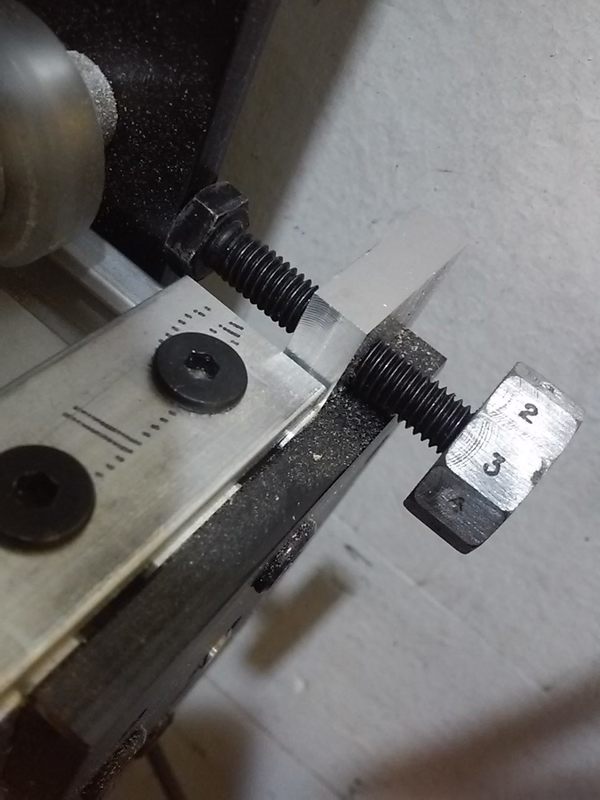
Note: Steppers/screws can move ever so slightly (<1.8 degrees) when turning on the drivers. This happens when the steppers move from a stopped micro step position to a full step start position. Because of this I do all settings and adjustments from the just turned on position.
For the initial stop screw setup the gantry is moved into reach of the stop screws, the drivers are turned off and back on, the stop screws are rotated until they contact the gantry plates, the 'heads' are set to 0 (setscrews facing up) and lightly locked in place.
After doing a two or five cut squaring, the resulting D(-r/l) number is used to adjust the appropriate head. The example was D- right 1.19mm. With the gantry in reach of the stop screws and the drivers just turned on, rotate the stop screws until they contact the gantry plates (should read the same number), loosen/rotate the offending 'head' clockwise by D-, e.g. 1 turn + 2 facets (1mm + .2mm) for the 1.19 example, and tighten the setscrews in both 'heads'.
To square the X-axis rotate the adjusted 'head' (e.g. right) back/counterclockwise to match the other head (e.g.1 turn + 2 facets), turn the drivers off and manually rotate the appropriate stepper (e.g. right) until the gantry plate bumps into the stop. Back the stops off, turn the drivers on and recheck the stops. Because of the above noted movement the 'heads' may not line up perfectly.
To tweak/adjust the X-axis turn the drivers off, back off the stops, manually rotate a stepper as needed until the 'heads' match (same number/position) when the stops are in contact with the X-axis plates. Getting things right on, finding the closest powered stepper positions, requires very small (1.8 degrees per full step) manual stepper movements. Once set, the 'heads' will read the same number (for days, weeks, whatever) until something goes wrong, i.e. steps are lost.
...A m5 x .8mm pitch stop screw might be a better choice with the stock WorkBee. The 8mm pitch drive screw divided by 200 full steps = .04mm per full step. A .8mm pitch stop screw divided by a 10 facet head = .08 per facet, i.e. a nice even two full steps per facet. In theory the set stops would always bump against the gantry plate with a facet (.08), or the point between facets (+/- .04), facing straight up.
...A 3D printed faceted setscrew head would make this a lot more practical. I'll draw/post a dimensioned plate drawing and send a set of plates to whomever sends me a usable 3D printed head and posts the drawing and head STL to Thingverse.
[ link | top ]