Home : Dalrun : T Slot :
 For an introduction to push stops, see my brief What is a push stop and Incremental Fence and Push Stop Accuracy YouTube videos... I suppose I should call these pivoting push stops to differentiate between swinging (e.g. Delta) and sliding (e.g. Blum) push stops.
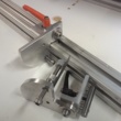
I made my first push stop about 10 years ago. The pictured stop is my most recent and feature rich incremental push stop. All my stops now have a base with two pins that mate with holes in a spring loaded self aligning t-slot nut. The incremental stops have longer pins that mate with incremental holes in a t-slot extrusion/fence (spacers can make them free sliding). While using an adjustable spindle for the actual material stop makes fine tuning free sliding stops a lot easier, its pretty much mandatory for an incremental stop.
Adjustable Spindles
Videos with pivoting push stops in use: dowels Rafix
Pivoting Push Stops
 For an introduction to push stops, see my brief What is a push stop and Incremental Fence and Push Stop Accuracy YouTube videos... I suppose I should call these pivoting push stops to differentiate between swinging (e.g. Delta) and sliding (e.g. Blum) push stops.
I made my first push stop about 10 years ago. The pictured stop is my most recent and feature rich incremental push stop. All my stops now have a base with two pins that mate with holes in a spring loaded self aligning t-slot nut. The incremental stops have longer pins that mate with incremental holes in a t-slot extrusion/fence (spacers can make them free sliding). While using an adjustable spindle for the actual material stop makes fine tuning free sliding stops a lot easier, its pretty much mandatory for an incremental stop.
Adjustable Spindles
Videos with pivoting push stops in use: dowels Rafix
Adjustable Spindles
I've come up with numerous adjustable spindle designs and all allow for adjusting the spindle the distance of one increment using fractional increments (e.g. 1/32" and 1mm). Metric spindles are easier because m6, 8 and 10 threads all can have a 1mm per turn thread pitch and divide evenly into .01mm sub increments. While 10-32 threads provide 1/32" per turn increments and 1/256" sub increments, they are a bit small in diameter and aren't suitable when working with decimals (e.g. metalworking)... but 1/4-20 is - .05" per turn and .005" sub increments.
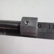
 Anyway, this particular design does not require a ruler, wrench, counting spindle turns or a precise fence to machine registration. The spindle has a scale, that matches the spindle thread pitch, and a faceted nut that serves as a pointer. When the setscrew in the nut faces forward, the end of the nut lines up with a mark on the scale. When the nut lines up with the 0 point on the scale (currently a 1" or 10cm mark), the face of the spindle will be centered on a hole in the incremental fence The facets/scale (10 facets for .01mm and ,005", 8 for 1/256") on the nut allow adjusting the spindle in fractional spindle increments. When the desired spindle protrusion is reached, the spindle is locked in place with a knurled thumb nut.
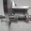
 The pictured stop is for 32mm increments. The m6 x 1mm spindle has a pointer nut with 10 facets allowing the spindle to be adjusted in 1mm +/- .01mm increments. When the pointer nut is set to 0 (10cm) the spindle protrudes an even increment, is 32mm from a locating pin. Two stops placed spindle face to spindle face will touch at the center of a fence hole. If the fence holes are not registered dead center to the machine (e.g. to boring machine bits), the stop spindles will need to be adjusted, right or left in equal full/fractional spindle increments, until they center on the machine. The pointer nuts can then be set to zero.
[ link | top ]
 Anyway, this particular design does not require a ruler, wrench, counting spindle turns or a precise fence to machine registration. The spindle has a scale, that matches the spindle thread pitch, and a faceted nut that serves as a pointer. When the setscrew in the nut faces forward, the end of the nut lines up with a mark on the scale. When the nut lines up with the 0 point on the scale (currently a 1" or 10cm mark), the face of the spindle will be centered on a hole in the incremental fence The facets/scale (10 facets for .01mm and ,005", 8 for 1/256") on the nut allow adjusting the spindle in fractional spindle increments. When the desired spindle protrusion is reached, the spindle is locked in place with a knurled thumb nut.
 The pictured stop is for 32mm increments. The m6 x 1mm spindle has a pointer nut with 10 facets allowing the spindle to be adjusted in 1mm +/- .01mm increments. When the pointer nut is set to 0 (10cm) the spindle protrudes an even increment, is 32mm from a locating pin. Two stops placed spindle face to spindle face will touch at the center of a fence hole. If the fence holes are not registered dead center to the machine (e.g. to boring machine bits), the stop spindles will need to be adjusted, right or left in equal full/fractional spindle increments, until they center on the machine. The pointer nuts can then be set to zero.
[ link | top ]
