
Home : Workshop : CNC :
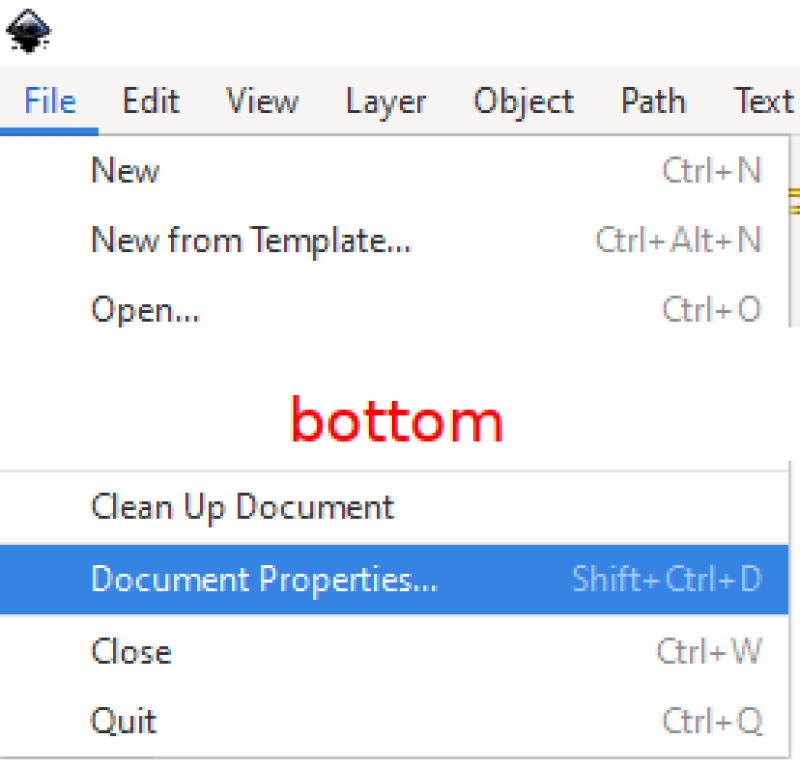
 I start with Document Properties (1st of 12 images) and enter a generous page Height and Width. The page and working (Display) units are separate, they can be different and changed at any time. The Scale = 1.0 page units need to be compatible with the CAM program (inches for Easel, Estlcam can be configured to accept any/all Inkscape units).
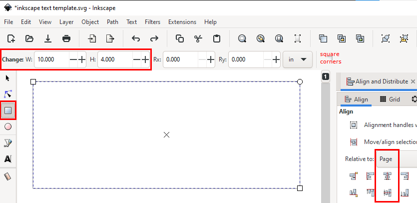
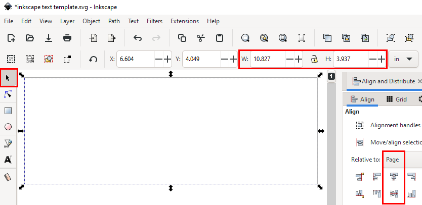
The first thing I draw is a material sized box using the Square tool. Click somewhere on the page, drag the mouse diagonally and release (click the 'square corners' icon if needed). Enter the desired dimensions and center the box on the page. The dimensions can be changed at any time using the Select tool for resizing. Note: Use Ctrl-click drag for square boxes (and round circles).
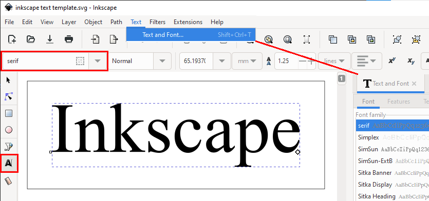
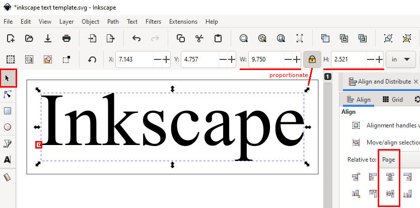
Use the Text tool to add/edit text. Fonts can be chosen from the searchable drop-down list or from the Text and Fonts dialog. Use the Select tool to resize and center the text. Use Ctrl-click-drag or click the lock icon to proportionately resize the text. At this point there will likely be some back and forth resizing and centering.
Use the Object to Path function to convert the text objects to paths. The only visible change to the text will be that there is no longer an anchor point (bottom of the I). While the text is still resizable, the font can no longer be changed.
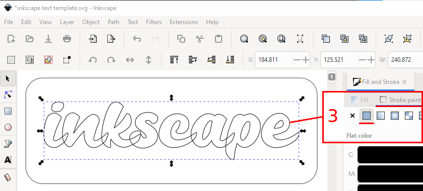
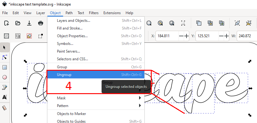
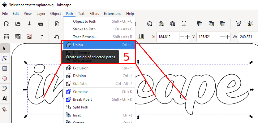
 With overlapping text, e.g. most script fonts, a few more steps are needed. After using the Object to Path function switch to the Fill and Stroke dialog, remove the Fill and add color to the stroke/path. Use Object : Ungroup to get individual letters and Path : Union to remove the overlaps and join/regroup the letters.
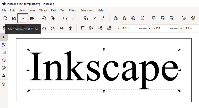
Save the file
[ comment | link | top ]
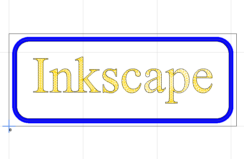
 Inkscape Path Effects can be used to add radiused or chamfered corners to a project. Adding corner details to boxes, e.g. for sign boards, is relatively easy. Radiusing corners for inlay projects (>= tool radius) may require more work, e.g. moving/editing nodes.
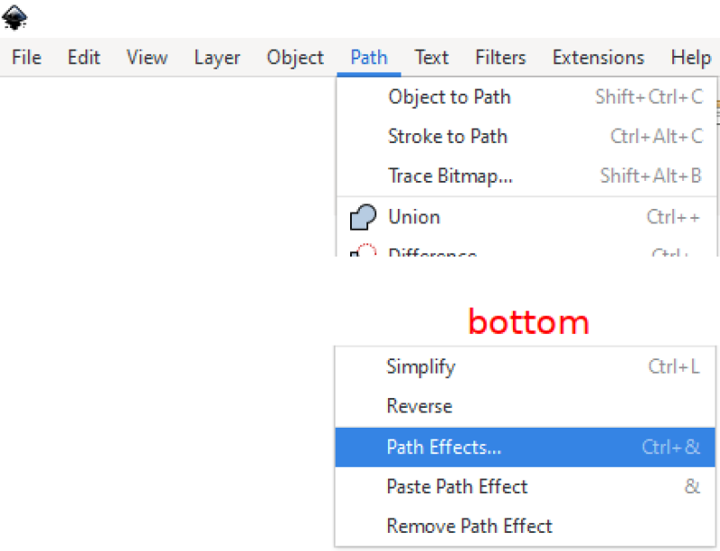
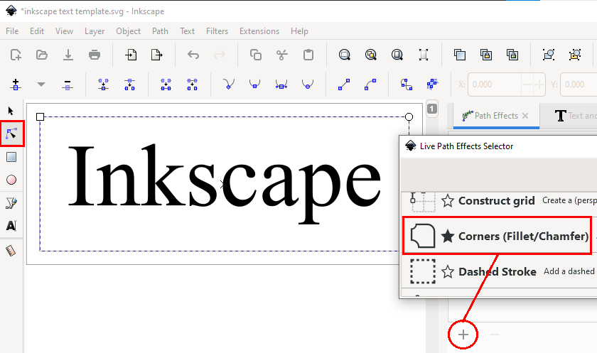
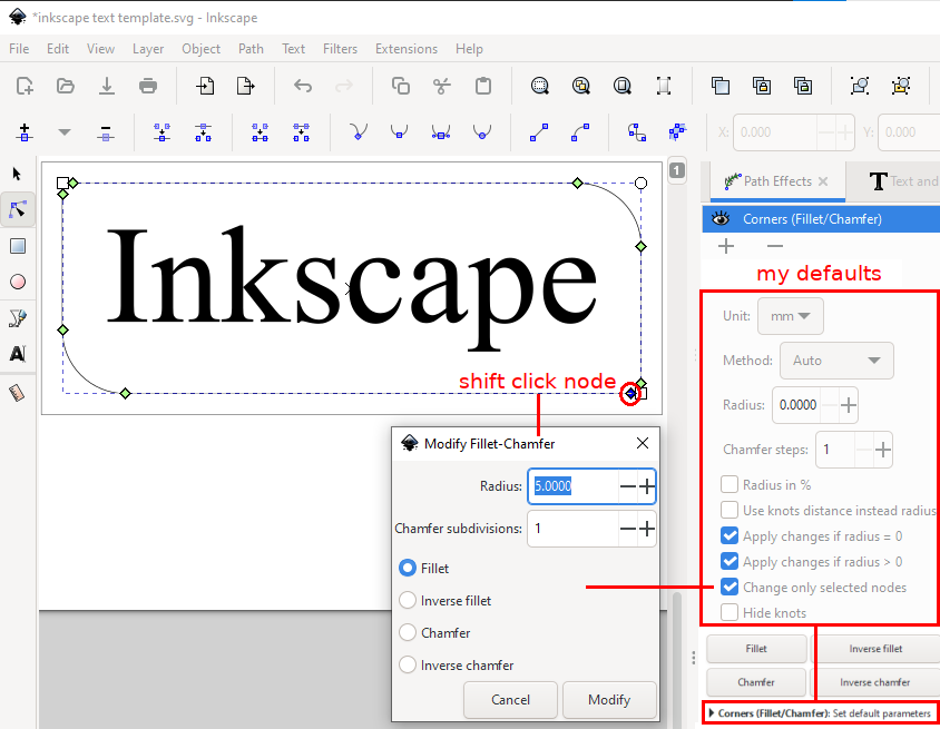
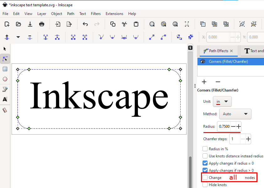
Select a box using the node tool. Open the Path Effects dialog, click the plus sign at the bottom of the dialog and choose Corners from the Live Path Effects Selector window. Using my default setup (click Corners default parameters to save) allows for applying the corner effects one by one (pretty much required when making an object inlay friendly). Deselecting Change only selected nodes will apply the same corner effect to all the corners of the selected object. The corner effect can be changed by clicking the Inverse fillet and Chamfer buttons in the dialog window. Entering a half height radius will create a 3 node half circle.
[ comment | link | top ]
Inkscape
Inkscape works well for text based CNC router projects. While it won't replace CAD, simple geometric projects are relatively painless. Inkscape 1.2 is a big step up from previous versions with new and easier to use features. While this page is about using Inkscape 1.2 for CNC Router projects, the focus is creating vector graphics for Estlcam (CAM).
This page looks kinda boring, but it's basically 25+ marked up screenshots (w/ prev/next buttons) and some explanatory text... added a few opened and ready to carve w/ Estlcam screenshots.
![]()
Setup
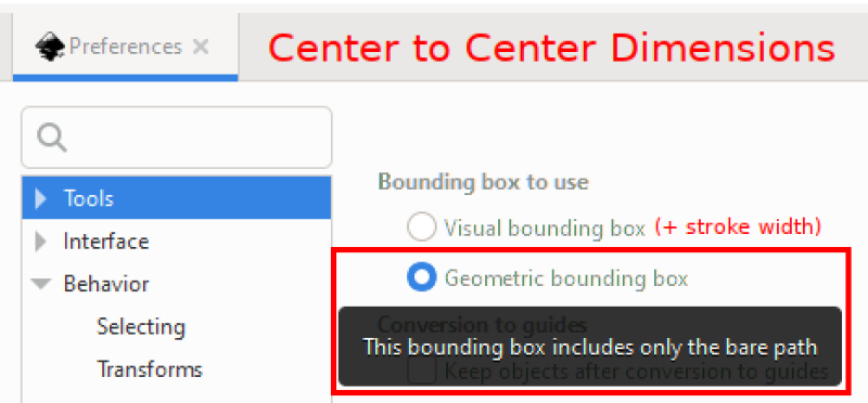
The default setup is for graphic artists where line/stroke width matters. To get center of the line/path dimensioning select the Preferences : Tools : Geometric bounding box (1st of 9 images).
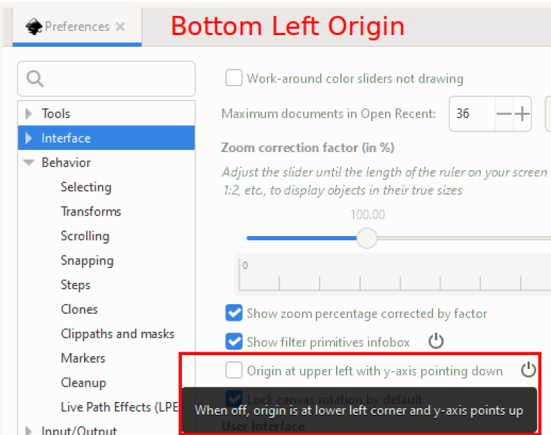
The default drawing origin is the top-left. To set it to the more common CAD/CAM bottom-left, deselect Preferences : Interface : Origin at upper left. This is only important when saving as DXF and inserting/adding (v11/12) additional layers into an Estlcam project file.
A cool feature of 1.2 is that it's easy hide tools you don't need/use from Preferences : Interface : Toolbars. The topics on this page will at least mention the usefulness of the Select, Node, Square, Circle, Line, Text, and Ruler tools.
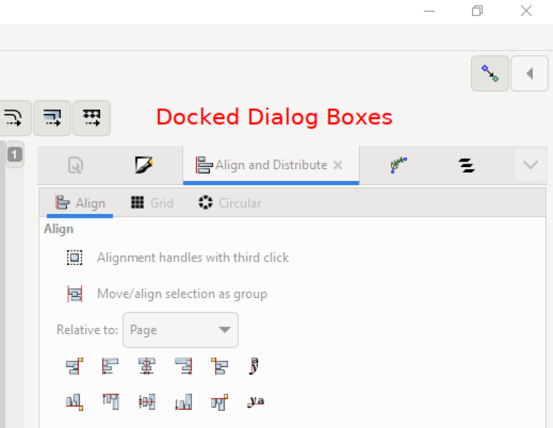
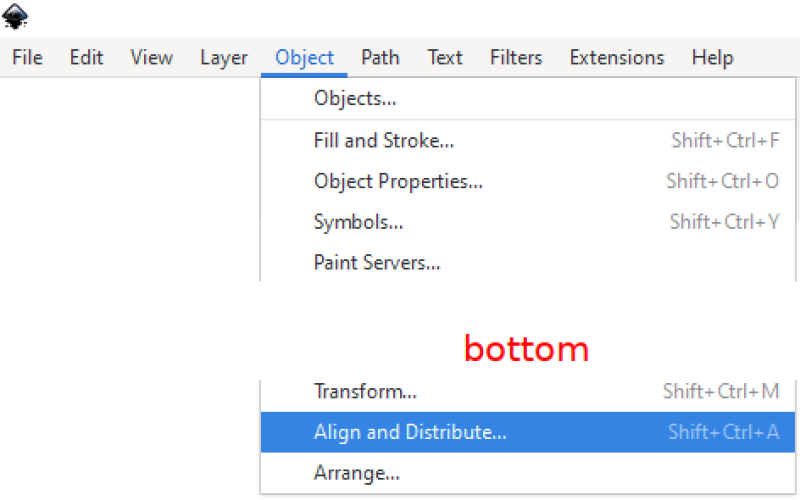
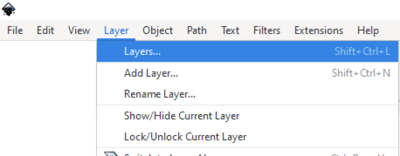
The right pane docked dialog boxes functionality is much improved in 1.2. This is a handy place for common tasks. The topics on this page will make use of: Align and Distribute, Document Properties, Fill and Stroke, Layers, and Path Effects. If the dialog box isn't docked, click its title button and drag/drop it in the side pane. The side pane can be sized and open/closed via its left drag bar/button.
[ comment | link | top ]
The default drawing origin is the top-left. To set it to the more common CAD/CAM bottom-left, deselect Preferences : Interface : Origin at upper left. This is only important when saving as DXF and inserting/adding (v11/12) additional layers into an Estlcam project file.
A cool feature of 1.2 is that it's easy hide tools you don't need/use from Preferences : Interface : Toolbars. The topics on this page will at least mention the usefulness of the Select, Node, Square, Circle, Line, Text, and Ruler tools.
The right pane docked dialog boxes functionality is much improved in 1.2. This is a handy place for common tasks. The topics on this page will make use of: Align and Distribute, Document Properties, Fill and Stroke, Layers, and Path Effects. If the dialog box isn't docked, click its title button and drag/drop it in the side pane. The side pane can be sized and open/closed via its left drag bar/button.
[ comment | link | top ]
Simple Text
 I start with Document Properties (1st of 12 images) and enter a generous page Height and Width. The page and working (Display) units are separate, they can be different and changed at any time. The Scale = 1.0 page units need to be compatible with the CAM program (inches for Easel, Estlcam can be configured to accept any/all Inkscape units).
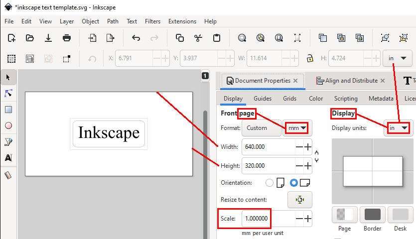
The first thing I draw is a material sized box using the Square tool. Click somewhere on the page, drag the mouse diagonally and release (click the 'square corners' icon if needed). Enter the desired dimensions and center the box on the page. The dimensions can be changed at any time using the Select tool for resizing. Note: Use Ctrl-click drag for square boxes (and round circles).
Use the Text tool to add/edit text. Fonts can be chosen from the searchable drop-down list or from the Text and Fonts dialog. Use the Select tool to resize and center the text. Use Ctrl-click-drag or click the lock icon to proportionately resize the text. At this point there will likely be some back and forth resizing and centering.
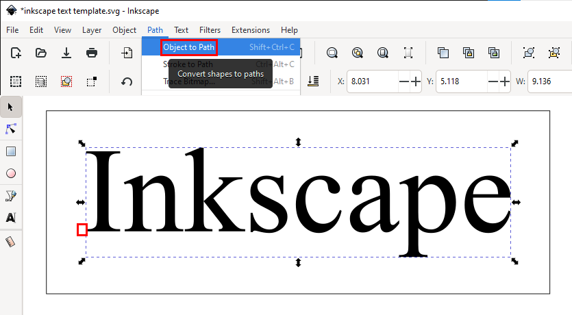
Use the Object to Path function to convert the text objects to paths. The only visible change to the text will be that there is no longer an anchor point (bottom of the I). While the text is still resizable, the font can no longer be changed.
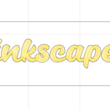
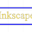
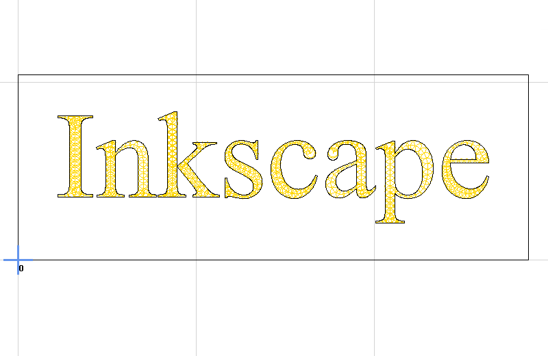
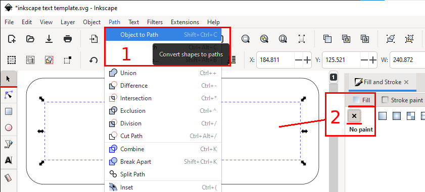
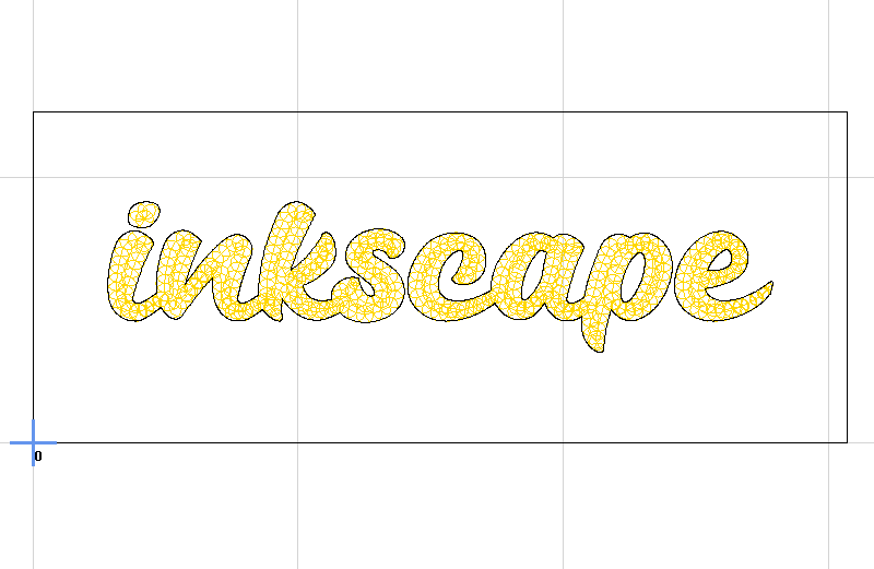 With overlapping text, e.g. most script fonts, a few more steps are needed. After using the Object to Path function switch to the Fill and Stroke dialog, remove the Fill and add color to the stroke/path. Use Object : Ungroup to get individual letters and Path : Union to remove the overlaps and join/regroup the letters.
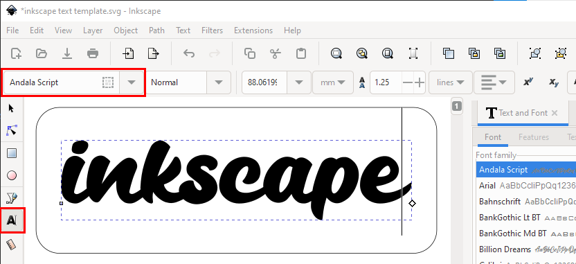
Save the file
[ comment | link | top ]
Corners
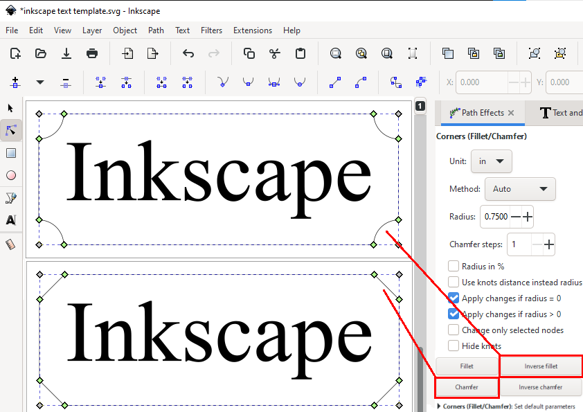
 Inkscape Path Effects can be used to add radiused or chamfered corners to a project. Adding corner details to boxes, e.g. for sign boards, is relatively easy. Radiusing corners for inlay projects (>= tool radius) may require more work, e.g. moving/editing nodes.
Select a box using the node tool. Open the Path Effects dialog, click the plus sign at the bottom of the dialog and choose Corners from the Live Path Effects Selector window. Using my default setup (click Corners default parameters to save) allows for applying the corner effects one by one (pretty much required when making an object inlay friendly). Deselecting Change only selected nodes will apply the same corner effect to all the corners of the selected object. The corner effect can be changed by clicking the Inverse fillet and Chamfer buttons in the dialog window. Entering a half height radius will create a 3 node half circle.
[ comment | link | top ]