
Home : Workshop : CNC :
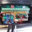
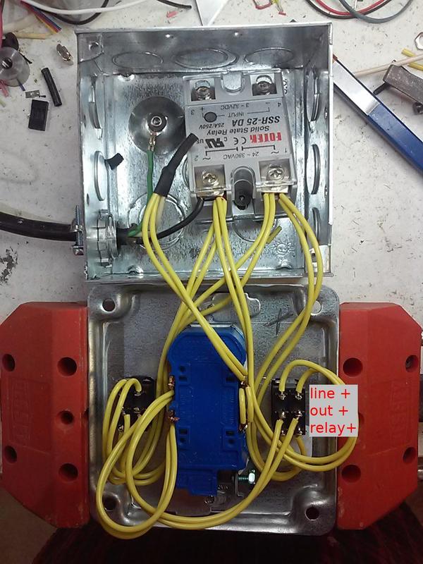
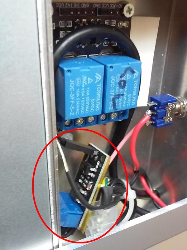
 My preference is to have the option of turning anything I might want to use on/off in sync with the start/end of a g-code program. To accomplish this I use two resistor/optocoupler circuits hooked up to the control board spindle run pins (~10ma). One is used as a simple switch to turn on the spindle (FWD>XGND), the other is the trigger circuit on a DC-DC relay. The relay triggers a (switched) 24v air solenoid and a ...two channel 50a solid state DC-AC relay (with pictured relay-on - off - line-on switches) to power my dust collector and vacuum pump.
[ link | top ]
 There are currently a plethora of cheap DC triggered DC and AC solid-state relays with load capacities from 10 to 100 amps. The SSR-[amps] DD (DC-DC), DA (DC-AC) or AA (AC-AC) relays should draw ~18ma max when triggered by an Arduino (5v). While great for powering AC equipment, the relays are a bit bulky so my current DC-DC relays are traditional coil relays.
...Most (eventually all) of my Arduino peripherals (e.g. this relay) are now 24v (stepper power supply) and switched via optocouplers (< 50ma loads) and a BJT (typ. <500ma) or Mosfet (> 1amp) as needed (no more coil relays). While I currently run this relay (~3.75ma load @24v) with an added BJT, switching it with an just an optocoupler (and 2 resistors) is on my to do list.
...A relay for a motor (inductive load, high start up current) should be rated 4 - 8x the motor's labeled run current, more for long run times without a heat sink.
[ link | top ]
 While a traditional two channel 5v coil relay can draw around 65ma (too much for an Ardino I/O pin), the required trigger current is quite low (typ < 5ma). The only relays that I have found with JD-VCC pins, an extra terminal that allows the coil to be externally powered, are "active low". To use both IN channels, the connected controller I/O pins need to be set low (enabled pin switches to gnd instead of 5v) and VCC needs to be powered from the controller 5v pin. If only one trigger signal is needed, a high I/O pin can be connected to VCC and an IN pin(s, both coils energized) can be connected to controller GND. The relay GND and JD-VCC pins are used to power the now isolated coil from an external source.
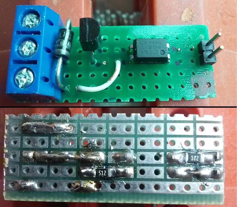
 ...Not being able to find a single channel version of the above relay I took a closer look at my 5v 2 channel high or low active relay (a 1 channel is available). Using the relays COM and IN terminals creates the same isolated COM/high/5v > r1k > optocoupler > IN/low/gnd trigger circuit as the above active low relay. The difference is that the optocoupler (2705) is bidirectional which also allows IN/high > optocoupler > r1k > COM/low. I tested both directions w/ 1.5, 3.7 and 5v and all triggered the coil (< 1.5v didn't). The hookup isn't pretty and the closeness of the COM pins to the coil +/- pins/traces bothers me, but a single channel is all I need and the smaller size might be worth it.
...I no longer use any electromagnetic relays.
[ link | top ]
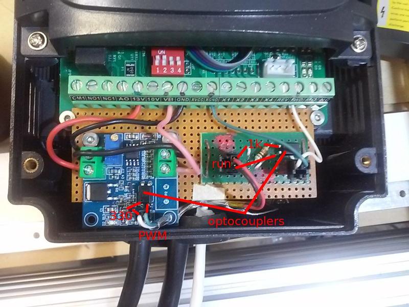
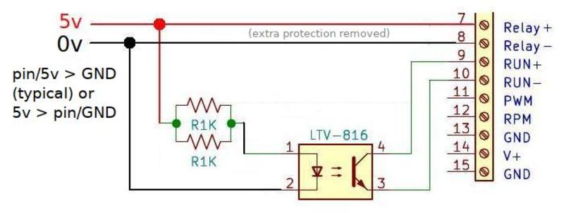
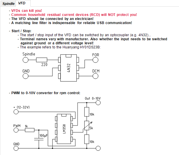
 Switching a spindle VFD via its FWD and (X)GND terminals does not require a relay per se, but isolating the controller from the VFD is preferred. When looking at the new Estlcam control board design I noticed that he uses a simple resistor and optocoupler to turn the spindle on ("run" VS mains). While he uses 500 ohms resistance (2 -1k), I used a 1k resistor in front of a PC817 optocoupler (cheap and easy to find) - which I later found out is the same as the trigger circuit on the above JD-VCC relay. As with the relay, the circuit can use a high or low I/O pin (to GND or 5v, respectively). My probably lousy math comes up with a 4ma load VS the relays stated 2ma. In any case, switching both the relay and VFD from the same Arduino pin is plenty safe (<10ma? - using a solid state relay would bump it close to 20ma)... Spindle control circuits from Estlcam software
[ link | top ]
 While an optocoupler can control a higher voltage, the load is typically limited to 50ma. Adding a transistor between the optocoupler and the load can easily increase the load capacity beyond the 10 amps of the above electromagnetic relays. Transistors alone can be used to switch higher volts/amps, but my goal is to keep my controller (Arduino) ground isolated from my 24v supply and VFD.
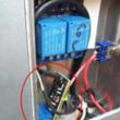
The transistors used can be MOSFETs (Metal-Oxide-Semiconductor Field-Effect Transistor, voltage controlled) or BJT's (Bipolar Junction Transistor, current controlled). With the specifics well out of my comfort zone I bought a cheap Isolated Mosfet module. The module is quite small yet probably overkill for the <250ma @ 24v needed by my air solenoid (200ma) and SSR-25-DA relay (3.75ma). The trigger circuit is once again a 1k resistor and PC817 optocoupler.
ProtoSupplies has detailed info about the LR7843 and D4184 boards, but not the AOD4184 (mine) or FR120N versions... They, and others, recommend a flyback diode on inductive loads (e.g. my solenoid). It's likely my SSR-25-DA would still be working if I had followed that advice sooner.
...I made a very similar isolated BJT switch (w/ flyback :-).
[ link | top ]
Relays
Relays are used to power anything needing more voltage and/or current than the CNC controller can provide. When using an Arduino a relay is needed to power anyhing needing more than 5v and/or anything hooked up to an I/O pin that uses more than 40ma. It is also a good idea to isolate any potentially 'noisy' circuits, e.g. relay coils and limit switches, from from the controller. This topic covers using solid-state, (isolated) electromagnet, optocoupler and transistor relays/switches with CNC controllers. While some of this topic is Arduino specific, most of it applies to any CNC controller.
Setup
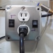
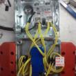
 My preference is to have the option of turning anything I might want to use on/off in sync with the start/end of a g-code program. To accomplish this I use two resistor/optocoupler circuits hooked up to the control board spindle run pins (~10ma). One is used as a simple switch to turn on the spindle (FWD>XGND), the other is the trigger circuit on a DC-DC relay. The relay triggers a (switched) 24v air solenoid and a ...two channel 50a solid state DC-AC relay (with pictured relay-on - off - line-on switches) to power my dust collector and vacuum pump.
[ link | top ]
Solid-state
 There are currently a plethora of cheap DC triggered DC and AC solid-state relays with load capacities from 10 to 100 amps. The SSR-[amps] DD (DC-DC), DA (DC-AC) or AA (AC-AC) relays should draw ~18ma max when triggered by an Arduino (5v). While great for powering AC equipment, the relays are a bit bulky so my current DC-DC relays are traditional coil relays.
...Most (eventually all) of my Arduino peripherals (e.g. this relay) are now 24v (stepper power supply) and switched via optocouplers (< 50ma loads) and a BJT (typ. <500ma) or Mosfet (> 1amp) as needed (no more coil relays). While I currently run this relay (~3.75ma load @24v) with an added BJT, switching it with an just an optocoupler (and 2 resistors) is on my to do list.
...A relay for a motor (inductive load, high start up current) should be rated 4 - 8x the motor's labeled run current, more for long run times without a heat sink.
[ link | top ]
Electromagnetic
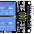
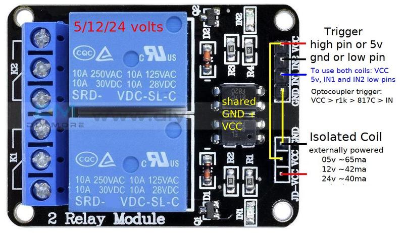 While a traditional two channel 5v coil relay can draw around 65ma (too much for an Ardino I/O pin), the required trigger current is quite low (typ < 5ma). The only relays that I have found with JD-VCC pins, an extra terminal that allows the coil to be externally powered, are "active low". To use both IN channels, the connected controller I/O pins need to be set low (enabled pin switches to gnd instead of 5v) and VCC needs to be powered from the controller 5v pin. If only one trigger signal is needed, a high I/O pin can be connected to VCC and an IN pin(s, both coils energized) can be connected to controller GND. The relay GND and JD-VCC pins are used to power the now isolated coil from an external source.
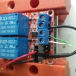
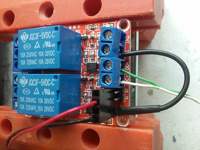 ...Not being able to find a single channel version of the above relay I took a closer look at my 5v 2 channel high or low active relay (a 1 channel is available). Using the relays COM and IN terminals creates the same isolated COM/high/5v > r1k > optocoupler > IN/low/gnd trigger circuit as the above active low relay. The difference is that the optocoupler (2705) is bidirectional which also allows IN/high > optocoupler > r1k > COM/low. I tested both directions w/ 1.5, 3.7 and 5v and all triggered the coil (< 1.5v didn't). The hookup isn't pretty and the closeness of the COM pins to the coil +/- pins/traces bothers me, but a single channel is all I need and the smaller size might be worth it.
...I no longer use any electromagnetic relays.
[ link | top ]
Optocoupler
 Switching a spindle VFD via its FWD and (X)GND terminals does not require a relay per se, but isolating the controller from the VFD is preferred. When looking at the new Estlcam control board design I noticed that he uses a simple resistor and optocoupler to turn the spindle on ("run" VS mains). While he uses 500 ohms resistance (2 -1k), I used a 1k resistor in front of a PC817 optocoupler (cheap and easy to find) - which I later found out is the same as the trigger circuit on the above JD-VCC relay. As with the relay, the circuit can use a high or low I/O pin (to GND or 5v, respectively). My probably lousy math comes up with a 4ma load VS the relays stated 2ma. In any case, switching both the relay and VFD from the same Arduino pin is plenty safe (<10ma? - using a solid state relay would bump it close to 20ma)... Spindle control circuits from Estlcam software
[ link | top ]
Transistor
 While an optocoupler can control a higher voltage, the load is typically limited to 50ma. Adding a transistor between the optocoupler and the load can easily increase the load capacity beyond the 10 amps of the above electromagnetic relays. Transistors alone can be used to switch higher volts/amps, but my goal is to keep my controller (Arduino) ground isolated from my 24v supply and VFD.
 The transistors used can be MOSFETs (Metal-Oxide-Semiconductor Field-Effect Transistor, voltage controlled) or BJT's (Bipolar Junction Transistor, current controlled). With the specifics well out of my comfort zone I bought a cheap Isolated Mosfet module. The module is quite small yet probably overkill for the <250ma @ 24v needed by my air solenoid (200ma) and SSR-25-DA relay (3.75ma). The trigger circuit is once again a 1k resistor and PC817 optocoupler.
ProtoSupplies has detailed info about the LR7843 and D4184 boards, but not the AOD4184 (mine) or FR120N versions... They, and others, recommend a flyback diode on inductive loads (e.g. my solenoid). It's likely my SSR-25-DA would still be working if I had followed that advice sooner.
...I made a very similar isolated BJT switch (w/ flyback :-).
[ link | top ]