
Home : Workshop : CNC : Estlcam :
 The Estlcam controller firmware can be installed on boards with with ATmega328 (e.g. Uno and Nano) or ATmega2560 (Mega) micro controllers. While an Arduino board and a simple screw shield is all that is required, there are numerous CNC specific shields and controller boards with added features (optoisolation, adjacent sig/gnd pins, etc.) that can make them more reliable. While there are only a few Estlcam specific boards, Estlcam can be installed on most? GRBL boards. The primary difference is the processor pin layout and Estlcam can be configured to use Estlcam or GRBL layouts.
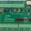
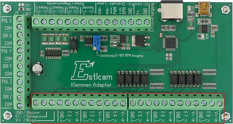
The Estlcam Terminal Adapter is the only Estlcam specific control board (pictured)... The only source I know of is Rocketronics and they no longer ship to the US... Rocketronics also has the new XL version that supports auto squaring. For specs and other new hardware see: Estlcam open source hardware. NOTE: Estcam v11 cannot be used with the new hardware (only v12).
[ comment | link | top ]
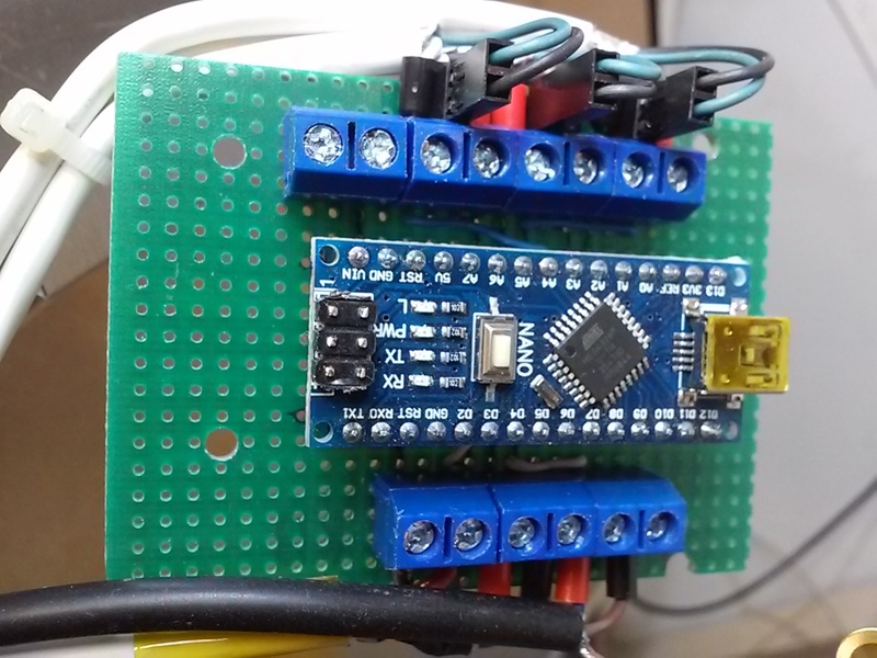
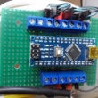 With no relatively inexpensive Estcam (or GRBL) pinout shields available to the US I've been making my own. The pictured Nano shield (w/o Nano) is the latest and currently supports drivers, probe, DC-AC relay/VFD run and VFD speed - all but the probe are isolated via external optocouplers (e.g. spindle run and PWM). While I have no need for them, I may add a daughter board for isolated limit switches (via 6 pin stacked header).
While I had been using pins and plugs and was planning on upgrading to latching plugs, the layout seemed to work better with screw terminals (the driver gnd pins/plugs were an as-built change). Especially on the crowded top row, using crimp ferrules makes it much easier to (re)hook things up reliably. The primary purpose of the design was having the signal and ground terminals next to each other to maximize shielding and minimize mess (not possible w/ a basic screw shield).
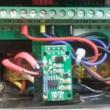
 ...My current shield has 24v > PC817 > Nano probe and limit inputs. I've also switched to a tidier stacked spindle control setup (GP8101 DAC on top).
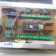
Estlcam USB errors* motivated me to rewire everything with shielded cables. I used two shielded pair 22awg sound/security cable for everything not in the drag chain. The cable allowed shielded signal/ground pairs from all external components (e.g. driver step/gnd and dir/gnd) all the way to the adjacent signal/ground terminals on the shield. The cable was also convenient for shielded 24v and ground pairs between the power supply and drivers - 2 x 22awg = 19awg.
*I used to have rare random days when I would get multiple USB errors. All were triggered when the spindle was under load and the repeats would all happen after a relatively small period of load on the spindle. After trying a lot of things (all shielded wires, VFD signaling optoisolation, etc.), I have reasonable confidence in it having been a grounding issue... It's now been some months of zero USB errors since running wires from power supply earth to the previously isolated X carriages/beam/stepper and the Z plate/stepper.
[ comment | link | top ]
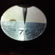 The calibration distance should be as big as possible, the closer to the axis limits the better. I used what I hope is an accurate steel rule and fixed one end (clamp just before 100mm/axis 0) securely to the spoilboard. Eyeball measurements aren't very accurate so I used a 20 degree engraving bit, a flashlight and a magnifier. Getting the flashlight centered behind the bit, getting the bit as low as possible and rotating the bit (because of the flutes, the tip appears to move from side to side and centering it in the grove can be tricky) all helped.
Estlcam storing the X/Y origin/coordinates makes adjustments to the distance per revolution (DPR) setting easy. My example distance was 650mm (axis zeroed @ 100 and moved to 750 on the ruler) and the controller coordinate read 649.91, i.e. .09mm shy. My 650 distance / my 8 DPR = 81.25 revolutions and 81.25 / .09 shy = .001 so I bumped my DPR from 8mm to 8.001 and after reprogramming the controller the coordinate read 649.99. In reality it was not that simple and the new coordinate may not match the math perfectly due to the changed revolutions (81.24@8.001 VS 81.25@81.25), but you can see how longer distances are more accurate (.09 @ 650 is only .014 @ 100mm).
Ruler distance / DPR = revolutions, (ruler +/- coordinate distance) / revolutions = DPR +/- distance
e.g. 650 / 8 = 81.25, (650 - 649.91) .09 / 81.25 = .001, 8 + .001 = 8.001 DPR
[ comment | link | top ]
Hardware
Controller Hardware
 The Estlcam controller firmware can be installed on boards with with ATmega328 (e.g. Uno and Nano) or ATmega2560 (Mega) micro controllers. While an Arduino board and a simple screw shield is all that is required, there are numerous CNC specific shields and controller boards with added features (optoisolation, adjacent sig/gnd pins, etc.) that can make them more reliable. While there are only a few Estlcam specific boards, Estlcam can be installed on most? GRBL boards. The primary difference is the processor pin layout and Estlcam can be configured to use Estlcam or GRBL layouts.
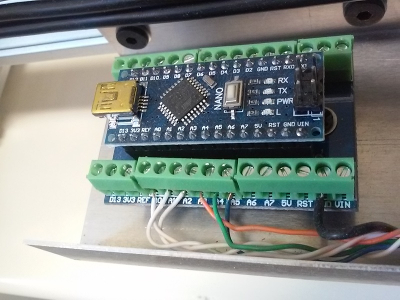
The Estlcam Terminal Adapter is the only Estlcam specific control board (pictured)... The only source I know of is Rocketronics and they no longer ship to the US... Rocketronics also has the new XL version that supports auto squaring. For specs and other new hardware see: Estlcam open source hardware. NOTE: Estcam v11 cannot be used with the new hardware (only v12).
[ comment | link | top ]
Nano Shield
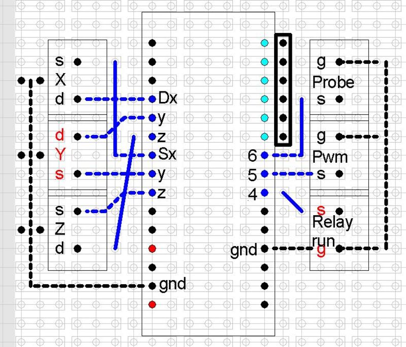
 With no relatively inexpensive Estcam (or GRBL) pinout shields available to the US I've been making my own. The pictured Nano shield (w/o Nano) is the latest and currently supports drivers, probe, DC-AC relay/VFD run and VFD speed - all but the probe are isolated via external optocouplers (e.g. spindle run and PWM). While I have no need for them, I may add a daughter board for isolated limit switches (via 6 pin stacked header).
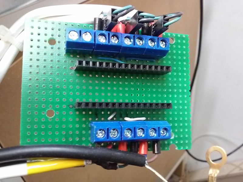
While I had been using pins and plugs and was planning on upgrading to latching plugs, the layout seemed to work better with screw terminals (the driver gnd pins/plugs were an as-built change). Especially on the crowded top row, using crimp ferrules makes it much easier to (re)hook things up reliably. The primary purpose of the design was having the signal and ground terminals next to each other to maximize shielding and minimize mess (not possible w/ a basic screw shield).
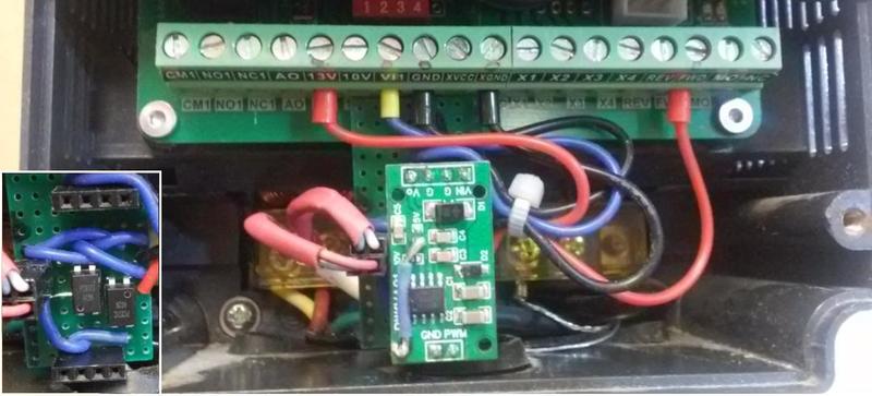
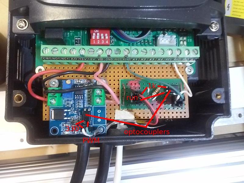
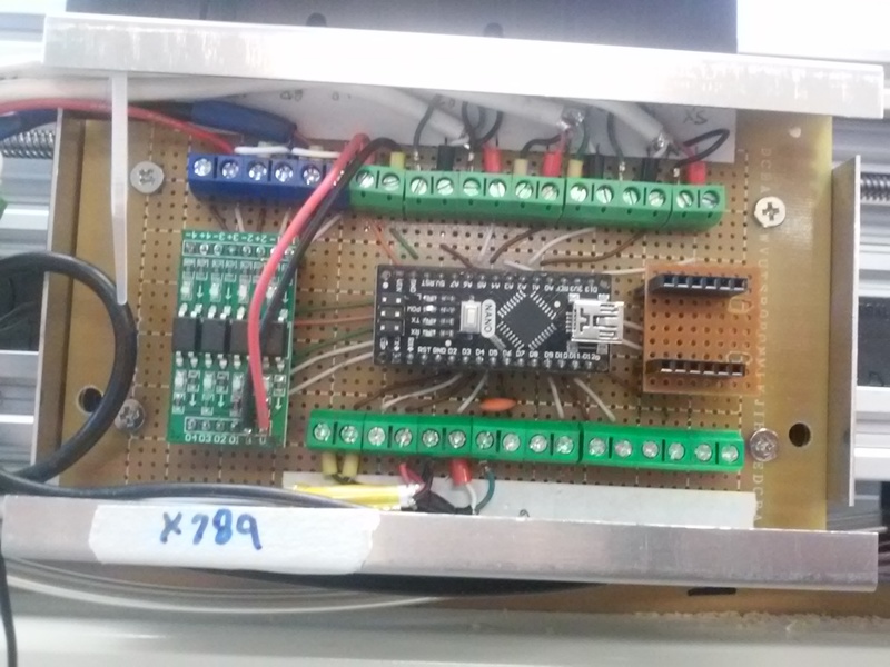 ...My current shield has 24v > PC817 > Nano probe and limit inputs. I've also switched to a tidier stacked spindle control setup (GP8101 DAC on top).
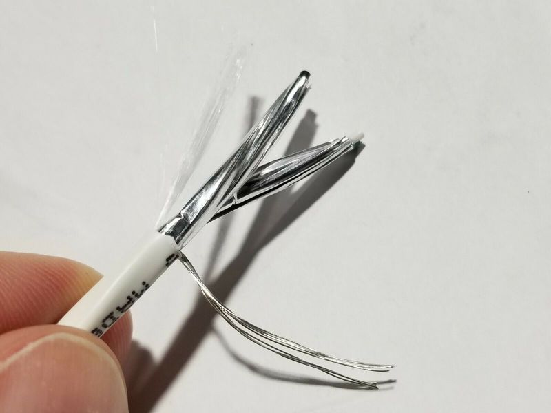
Estlcam USB errors* motivated me to rewire everything with shielded cables. I used two shielded pair 22awg sound/security cable for everything not in the drag chain. The cable allowed shielded signal/ground pairs from all external components (e.g. driver step/gnd and dir/gnd) all the way to the adjacent signal/ground terminals on the shield. The cable was also convenient for shielded 24v and ground pairs between the power supply and drivers - 2 x 22awg = 19awg.
*I used to have rare random days when I would get multiple USB errors. All were triggered when the spindle was under load and the repeats would all happen after a relatively small period of load on the spindle. After trying a lot of things (all shielded wires, VFD signaling optoisolation, etc.), I have reasonable confidence in it having been a grounding issue... It's now been some months of zero USB errors since running wires from power supply earth to the previously isolated X carriages/beam/stepper and the Z plate/stepper.
[ comment | link | top ]
Axis Calibration
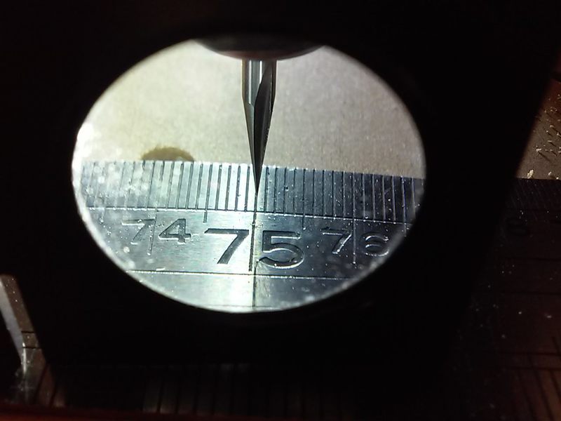 The calibration distance should be as big as possible, the closer to the axis limits the better. I used what I hope is an accurate steel rule and fixed one end (clamp just before 100mm/axis 0) securely to the spoilboard. Eyeball measurements aren't very accurate so I used a 20 degree engraving bit, a flashlight and a magnifier. Getting the flashlight centered behind the bit, getting the bit as low as possible and rotating the bit (because of the flutes, the tip appears to move from side to side and centering it in the grove can be tricky) all helped.
Estlcam storing the X/Y origin/coordinates makes adjustments to the distance per revolution (DPR) setting easy. My example distance was 650mm (axis zeroed @ 100 and moved to 750 on the ruler) and the controller coordinate read 649.91, i.e. .09mm shy. My 650 distance / my 8 DPR = 81.25 revolutions and 81.25 / .09 shy = .001 so I bumped my DPR from 8mm to 8.001 and after reprogramming the controller the coordinate read 649.99. In reality it was not that simple and the new coordinate may not match the math perfectly due to the changed revolutions (81.24@8.001 VS 81.25@81.25), but you can see how longer distances are more accurate (.09 @ 650 is only .014 @ 100mm).
Ruler distance / DPR = revolutions, (ruler +/- coordinate distance) / revolutions = DPR +/- distance
e.g. 650 / 8 = 81.25, (650 - 649.91) .09 / 81.25 = .001, 8 + .001 = 8.001 DPR
[ comment | link | top ]