
Home : Workshop : CNC : Estlcam :
 The G-code that the Estlcam CAM program generates needs to be compatible with the motion control firmware (to be) installed on the controller board (Estlcam, GRBL, or other). Start by clicking the appropriate motion controller. A few of the options will be controller specific and the choices here will affect the CNC Program (CAM and control) and (Estlcam installed on the) CNC Controller settings.
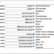
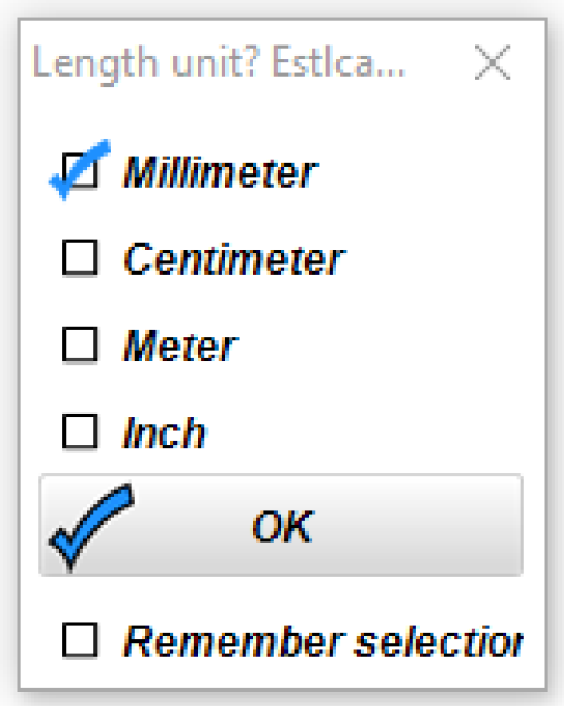
Units of Measure
-The "Ask each time" import units option is the most flexible (SVG, DXF and STL)
Both CNC Program (Estlcam generated G-code) and Estlcam (everything else) units are typically set to millimeters or inches and per minute. The settings can be changed on the fly to import (Open) or export (Save CNC program) G-code in different units, e.g. change Estlcam units temporarily so that you can machine inch (G20) G-code on a normally metric machine.
-The CNC Program length and feed units need to match what the motion controller (Estlcam or other) is expecting.
-The Estlcam length and feed units need to match the G-code (generated by Estlcam or other) being machined.
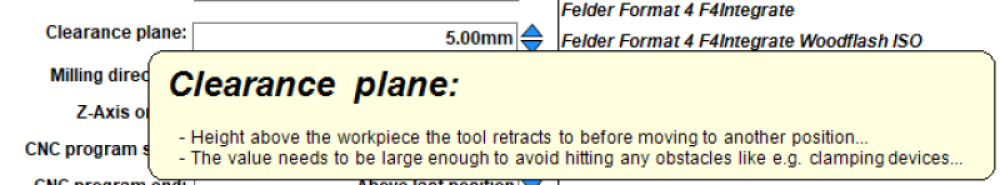
Clearance Plane
High enough to clear all clamping devices
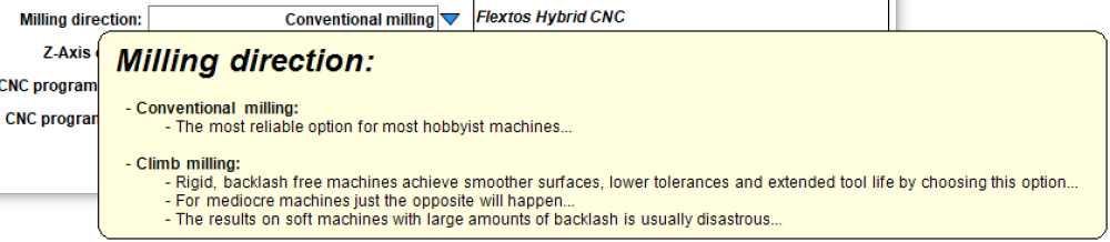
Milling Direction
Conventional unless it's a pretty darn stiff and tight machine
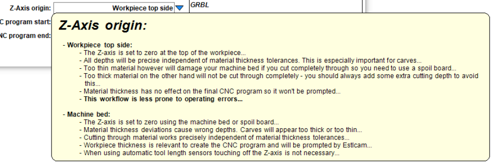
Z Axis Origin
Material top is almost always the easiest
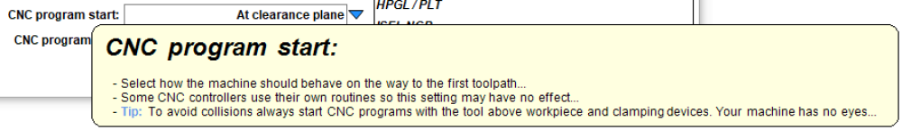
CNC Program Start
At clearance plane allows the spindle to skip the origin and go directly to the cut start
CNC Program End
Both Start and End can be customized using Setup : CNC Programs : Texts
[ comment | link | top ]
 It's probably a good idea to once again select the appropriate controller and make sure the length and feed units match those on the Basic Settings page. The other settings will depend on the controller selected (e.g. I don't think Easel supports arc commands). The rest of the tabs allow for some pretty fine grained customization and shouldn't need to be changed.
[ comment | link | top ]
 If Estlcam was chosen earlier, the board needs to be configured and programmed. The first thing to do is select the appropriate hardware. All compatible hardware is built around an 8-bit ATmega microprocessor. The Estlcam and GRBL pinouts define which processor pins are used for what signals, e.g. stepper pulse and direction. Either pinout can be used if the board terminals have processor pin labels, e.g. A0-5 (Uno, Nano, etc.). All boards made for Estlcam (official or not) use the Estlcam pinout. Most current GRBL boards have a PWM terminal (spindle speed) and a 0.9-1.1 pinout (e.g. Shapeoko and CNC Shield V3.51). The V3 CNC Shields are pretty dated (0.8 compatible). I'm guessing the Ramps, Bobs, Spark, etc. options will automatically configure most of the following.
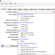
USB / COM port
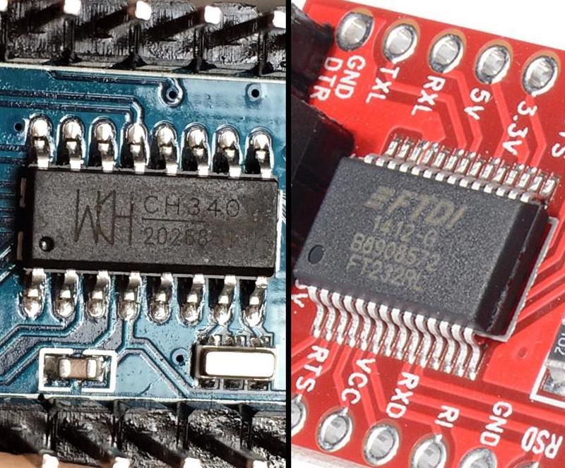
If the board is not found a driver likely needs to be installed.
Drivers for FTDI (real) and WCH (clones) serial chips are the most common.
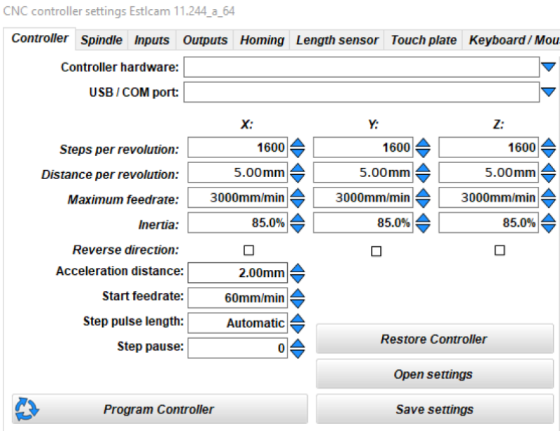
 I'm pretty sure the image reflects the current (v11) default X,Y,Z settings. Click Program Controller after making changes. Note: Estlcam v8 (old) instructions say to disconnect all but the steppers/drivers (spindle control, limit switches, etc.) before programming. I've never done this and had no issues, but it could be a good idea when first installing Estlcam on unfamiliar hardware.
Primary Settings
Check and adjust these until the machine can jog smoothly and accurately at Maximum Feedrate.
These are the only changes I have needed to make for my Workbee and a Shapeoko.
(8 and 40mm per revolution, 4k and 5k Feedrate, both at 1.6k steps)
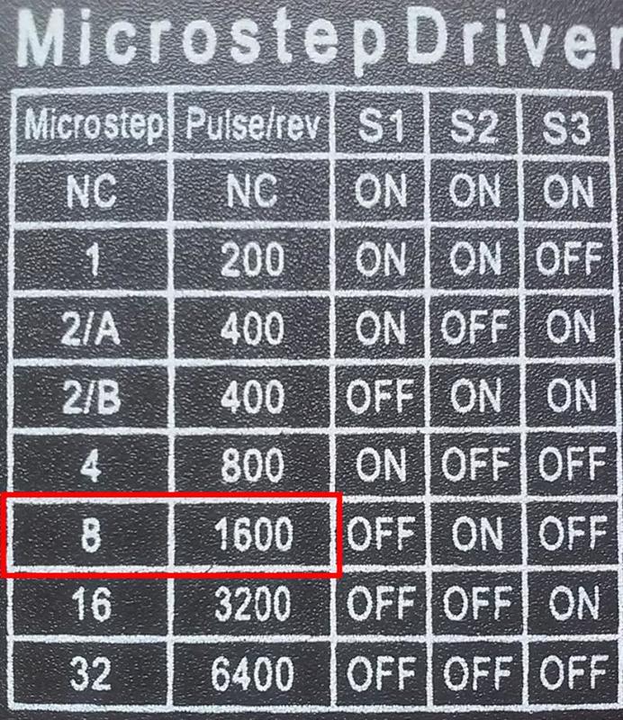
Steps per Revolution (1600)
200 full steps (typical stepper) x 8 driver microsteps (AKA 1/8 or 1:8) = 1600 steps per revolution of the stepper motor.
Set the hardware/drivers to match this setting (or vice versa).
1600 is recommended and fairly common, e.g. Shapeoko and X-Carve.
If you cannot find/set driver microsteps, Distance per revolution x GRBL $100 $101 $102 setting = Steps per revolution.
This should be a full number, no decimal places.
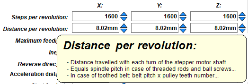
Distance per Revolution
Distance that the machine/axis/spindle moves per revolution of the stepper motor.
Example settings:
Screw: 8mm lead = 8mm, 5mm pitch x 2 start = 10mm (lead)
Belt: 2mm pitch x 20 tooth pulley = 40mm
Rack: 79.8mm pinion circumference (pi x dia) / 3 (60 / 20 tooth) reduction = 26.6mm
Rotate a stepper a full turn to confirm that the machine moves the expected distance
This number may need to be tweaked (3-4 decimal places is fine), see: Axis Calibration
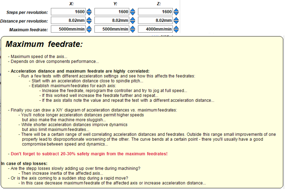
Maximum Feedrate
3000mm/min is a reasonably low maximum, the minimum is 2% of this (60mm/min).
When first testing the machine start at the lowest speed (base of the arrows) and ramp the speed up.
Increase and/or decrease this setting (must reprogram) until no steps are lost (no stutters/stalls).
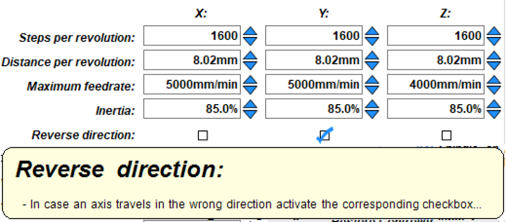
Reverse Direction
If any axis is moving in the wrong direction, click the appropriate box and reprogram.
Fine Tuning
Changing these is unlikely to be needed, but could improve performance.
My comments are no experience interpretations, click the names to view the tooltips.
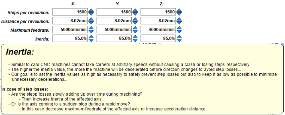
Inertia (85%)
Increase if machining a series of 90 degree corners results in accumulating step losses.
Cutting something like a 20 x 20 x 20mm 8 pass square pocket might be a good test
Acceleration Distance (2mm)
Use this to tweak the balance point between feed speeds and machine responsiveness.
Increasing this may allow higher feedrates at the expense of a less responsive machine.
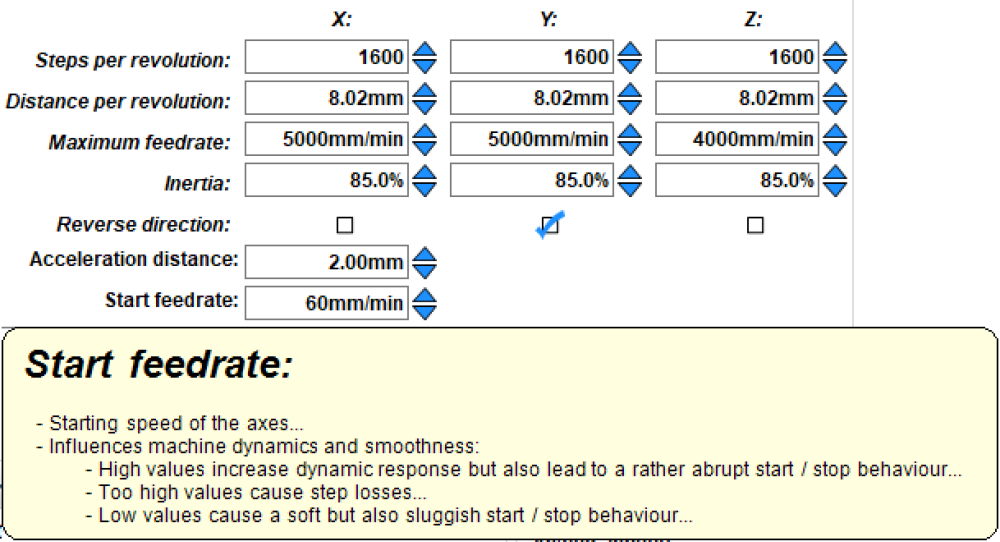
Start Feedrate (60mm/min)
Use this to tweak machine responsiveness; higher leans to jerky, lower to sluggish.
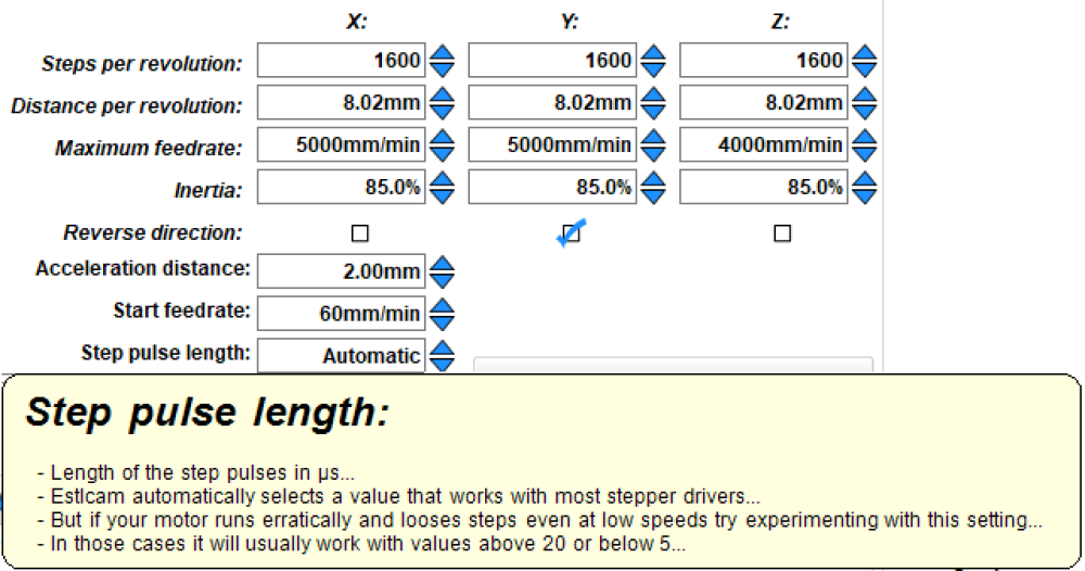
Step Pulse Length (Automatic)
Automatic works best for all but a few drivers that have very low step frequency limits (<5uS?).
Try changing this if stepper movement is erratic and there are low speed step losses (@1k jog?).
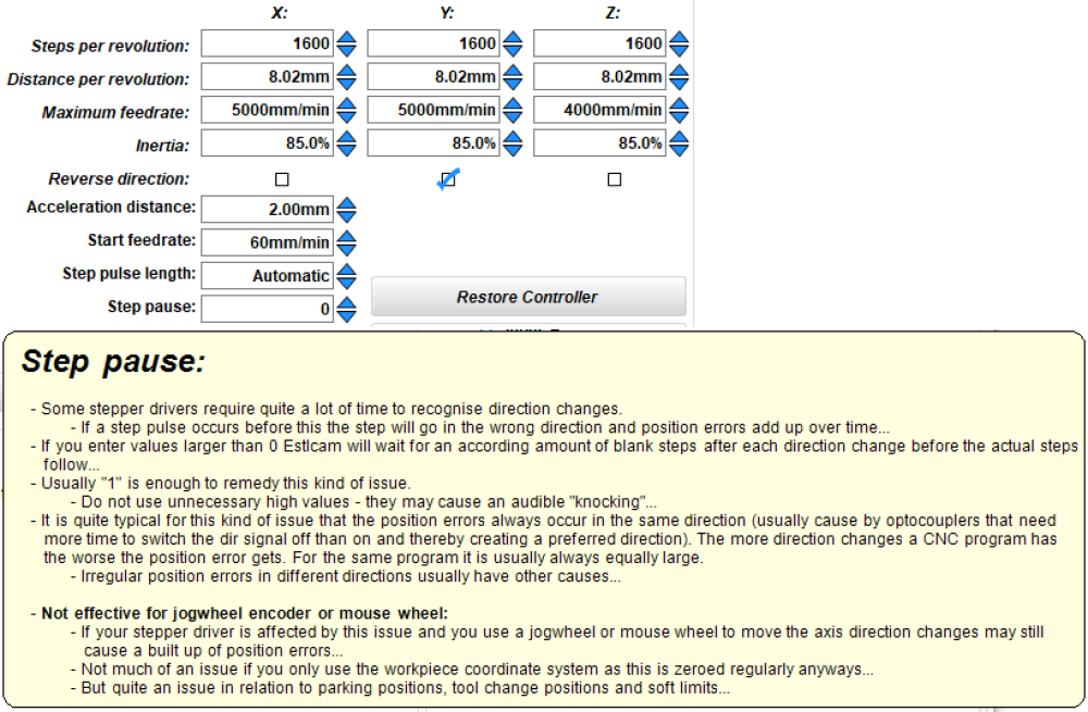
Step Pause (0)
If a single axis has accumulated positioning errors try setting it to 1.
[ comment | link | top ]
Setup
 This page is an attempt to cover at least the basics of the Estlcam Setup menu. While I'll try and cover using Estlcam for CAM or motion control (one or the other), I've only used it for creating and machining G-code (both). All but one of the setting names on this page link to images that include the tooltip for that setting. While all the images are from v11, the settings covered on this page also apply to v12.
The Estlcam 8 - USB CNC controller (English) YouTube video is a bit out of date, but most of the information still applies.
![]()
Basic Settings
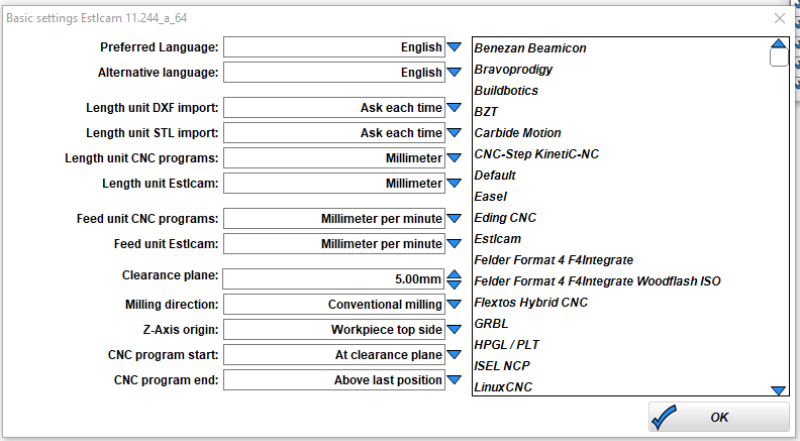 The G-code that the Estlcam CAM program generates needs to be compatible with the motion control firmware (to be) installed on the controller board (Estlcam, GRBL, or other). Start by clicking the appropriate motion controller. A few of the options will be controller specific and the choices here will affect the CNC Program (CAM and control) and (Estlcam installed on the) CNC Controller settings.
Units of Measure
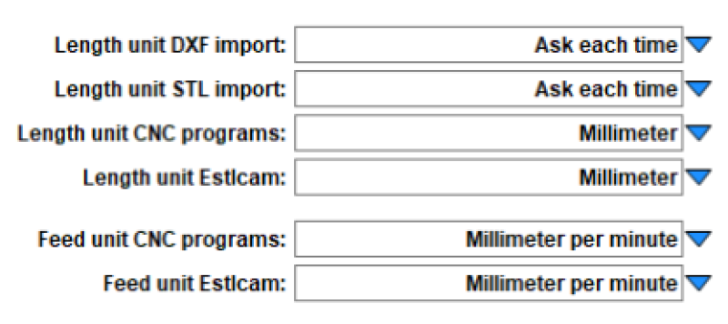
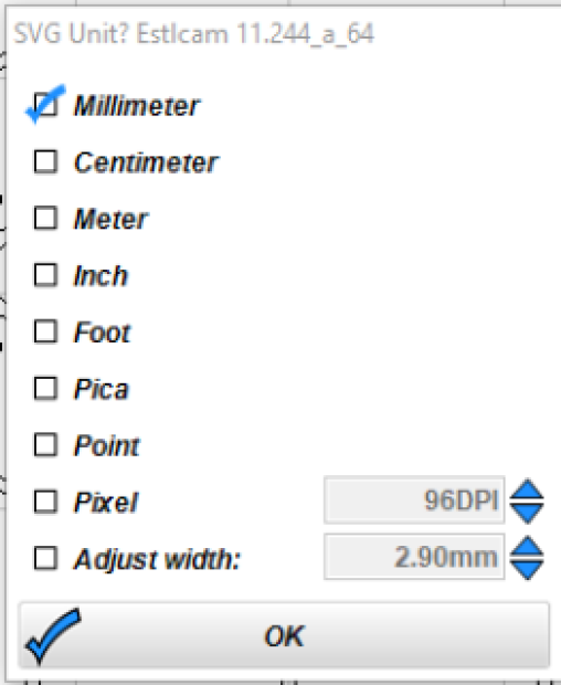
-The "Ask each time" import units option is the most flexible (SVG, DXF and STL)
Both CNC Program (Estlcam generated G-code) and Estlcam (everything else) units are typically set to millimeters or inches and per minute. The settings can be changed on the fly to import (Open) or export (Save CNC program) G-code in different units, e.g. change Estlcam units temporarily so that you can machine inch (G20) G-code on a normally metric machine.
-The CNC Program length and feed units need to match what the motion controller (Estlcam or other) is expecting.
-The Estlcam length and feed units need to match the G-code (generated by Estlcam or other) being machined.
Clearance Plane
High enough to clear all clamping devices
Milling Direction
Conventional unless it's a pretty darn stiff and tight machine
Z Axis Origin
Material top is almost always the easiest
CNC Program Start
At clearance plane allows the spindle to skip the origin and go directly to the cut start
CNC Program End
Both Start and End can be customized using Setup : CNC Programs : Texts
[ comment | link | top ]
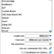
CNC Programs
 It's probably a good idea to once again select the appropriate controller and make sure the length and feed units match those on the Basic Settings page. The other settings will depend on the controller selected (e.g. I don't think Easel supports arc commands). The rest of the tabs allow for some pretty fine grained customization and shouldn't need to be changed.
[ comment | link | top ]
CNC Controller
 If Estlcam was chosen earlier, the board needs to be configured and programmed. The first thing to do is select the appropriate hardware. All compatible hardware is built around an 8-bit ATmega microprocessor. The Estlcam and GRBL pinouts define which processor pins are used for what signals, e.g. stepper pulse and direction. Either pinout can be used if the board terminals have processor pin labels, e.g. A0-5 (Uno, Nano, etc.). All boards made for Estlcam (official or not) use the Estlcam pinout. Most current GRBL boards have a PWM terminal (spindle speed) and a 0.9-1.1 pinout (e.g. Shapeoko and CNC Shield V3.51). The V3 CNC Shields are pretty dated (0.8 compatible). I'm guessing the Ramps, Bobs, Spark, etc. options will automatically configure most of the following.
USB / COM port
If the board is not found a driver likely needs to be installed.
Drivers for FTDI (real) and WCH (clones) serial chips are the most common.
 I'm pretty sure the image reflects the current (v11) default X,Y,Z settings. Click Program Controller after making changes. Note: Estlcam v8 (old) instructions say to disconnect all but the steppers/drivers (spindle control, limit switches, etc.) before programming. I've never done this and had no issues, but it could be a good idea when first installing Estlcam on unfamiliar hardware.
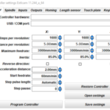
Primary Settings
Check and adjust these until the machine can jog smoothly and accurately at Maximum Feedrate.
These are the only changes I have needed to make for my Workbee and a Shapeoko.
(8 and 40mm per revolution, 4k and 5k Feedrate, both at 1.6k steps)
Steps per Revolution (1600)
200 full steps (typical stepper) x 8 driver microsteps (AKA 1/8 or 1:8) = 1600 steps per revolution of the stepper motor.
Set the hardware/drivers to match this setting (or vice versa).
1600 is recommended and fairly common, e.g. Shapeoko and X-Carve.
If you cannot find/set driver microsteps, Distance per revolution x GRBL $100 $101 $102 setting = Steps per revolution.
This should be a full number, no decimal places.
Distance per Revolution
Distance that the machine/axis/spindle moves per revolution of the stepper motor.
Example settings:
Screw: 8mm lead = 8mm, 5mm pitch x 2 start = 10mm (lead)
Belt: 2mm pitch x 20 tooth pulley = 40mm
Rack: 79.8mm pinion circumference (pi x dia) / 3 (60 / 20 tooth) reduction = 26.6mm
Rotate a stepper a full turn to confirm that the machine moves the expected distance
This number may need to be tweaked (3-4 decimal places is fine), see: Axis Calibration
Maximum Feedrate
3000mm/min is a reasonably low maximum, the minimum is 2% of this (60mm/min).
When first testing the machine start at the lowest speed (base of the arrows) and ramp the speed up.
Increase and/or decrease this setting (must reprogram) until no steps are lost (no stutters/stalls).
Reverse Direction
If any axis is moving in the wrong direction, click the appropriate box and reprogram.
Fine Tuning
Changing these is unlikely to be needed, but could improve performance.
My comments are no experience interpretations, click the names to view the tooltips.
Inertia (85%)
Increase if machining a series of 90 degree corners results in accumulating step losses.
Cutting something like a 20 x 20 x 20mm 8 pass square pocket might be a good test
Acceleration Distance (2mm)
Use this to tweak the balance point between feed speeds and machine responsiveness.
Increasing this may allow higher feedrates at the expense of a less responsive machine.
Start Feedrate (60mm/min)
Use this to tweak machine responsiveness; higher leans to jerky, lower to sluggish.
Step Pulse Length (Automatic)
Automatic works best for all but a few drivers that have very low step frequency limits (<5uS?).
Try changing this if stepper movement is erratic and there are low speed step losses (@1k jog?).
Step Pause (0)
If a single axis has accumulated positioning errors try setting it to 1.
[ comment | link | top ]